
SKF Oil Injection Method
Makes bearing mounting an easy task
Easy, quick and effortless bearing dismounting
When using the SKF Oil Injection Method, the mating surfaces are separated by a thin film of oil injected under high pressure, thereby virtually eliminating the friction between them. The method is versatile as it can be used for dismounting bearings and other components mounted on either cylindrical or tapered seatings. When dismounting bearings mounted on cylindrical seatings, the injected oil can reduce the required pulling forces by up to 90%. Subsequently, the physical effort required when using a puller to remove the bearing from its seating is significantly reduced.
When using the SKF Oil Injection Method to dismount bearings mounted on tapered seatings, the interference fit is completely overcome by the injected oil. The bearing is then ejected from the seating with great force, making the use of a puller unnecessary. In this case, a stop-nut must be used to control the ejection of the bearing. The SKF Oil Injection Method, which is used for many bearing applications, can also be used in other applications, such as:
Couplings
Gear wheels
Railway wheels
Propellers
Built-up crankshafts
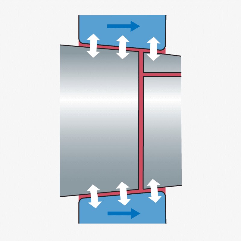
Mounting – Tapered shafts
The concept
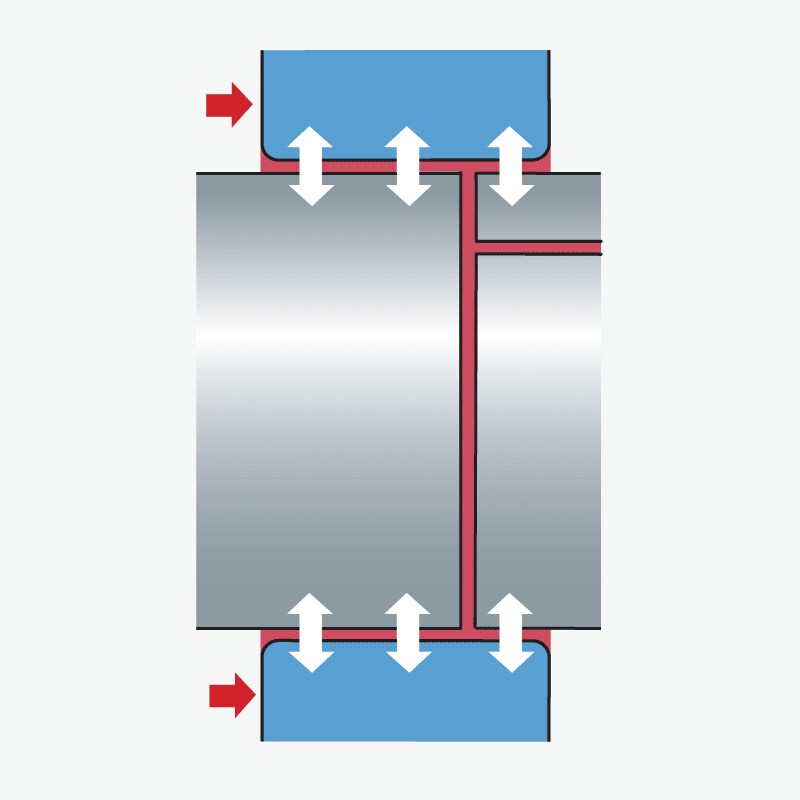
Injecting oil between two tapered surfaces creates a thin oil film, which reduces the friction between them, thereby significantly reducing the mounting force required. The thin oil film also minimises the risk of metallic contact when mounting, reducing the risk of component damage (fig 1).
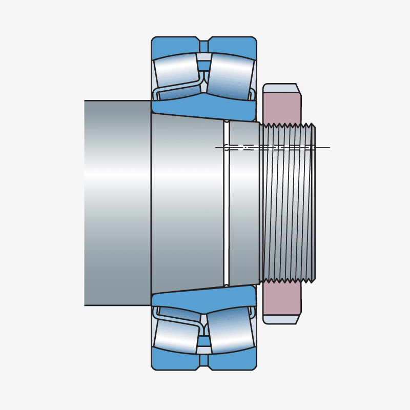
The preparation
During manufacture, the shafts are prepared with oil ducts and grooves. For technical information on how to prepare the shafts, consult an SKF application engineer (fig 2).
The action
Bearings are mounted by pushing them up the shaft with the aid of an SKF HMV .. E nut. The force to mount the bearing is reduced if oil is injected between the shaft and the bearing. This is often done with larger size bearings (fig 3).
Dismounting – Cylindrical shafts
The concept
By injecting oil of a certain viscosity between two shrink fitted surfaces, the mating surfaces will become separated by a thin oil film. The dismounting force required is thus greatly reduced. The thin oil film also minimises the risk of metallic contact when dismounting, reducing the risk of component damage (fig 4).
The preparation
During manufacture, the shafts are prepared with oil ducts and grooves. For technical information on how to prepare the shafts, consult an SKF application engineer (fig 5).
The action
Dismounting the bearing is made easier by pumping oil under pressure between the mating surfaces. Once the oil pressure has built up, the component can be removed from the shaft with a minimum of effort (fig 6).
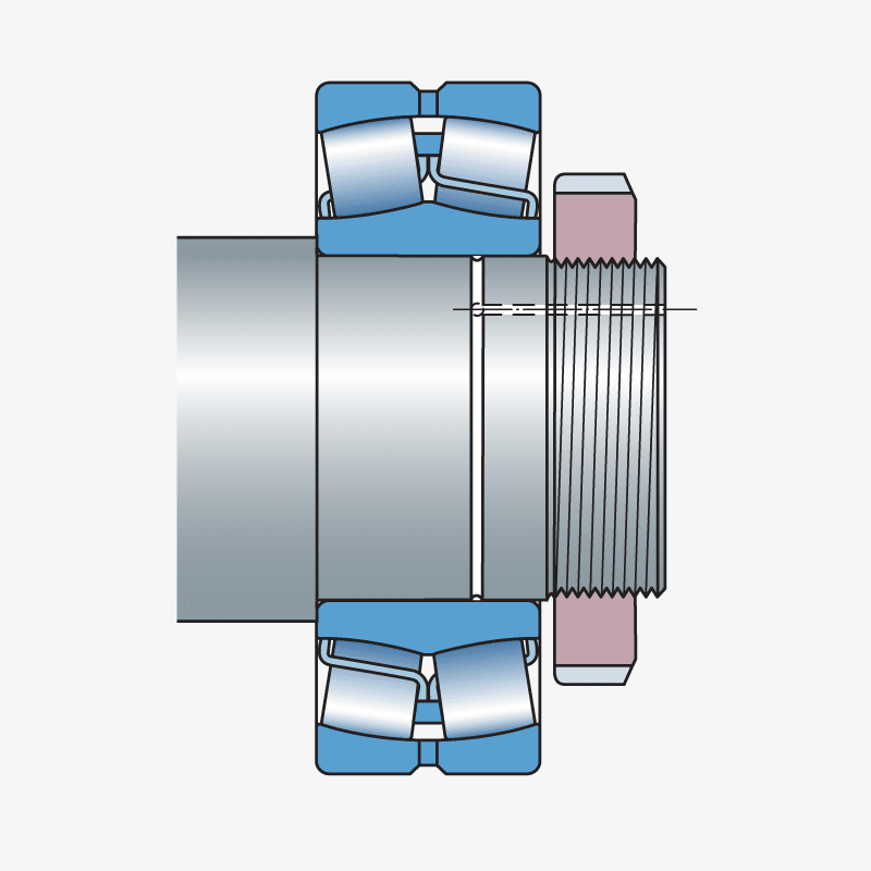
Dismounting – Tapered shafts
The concept
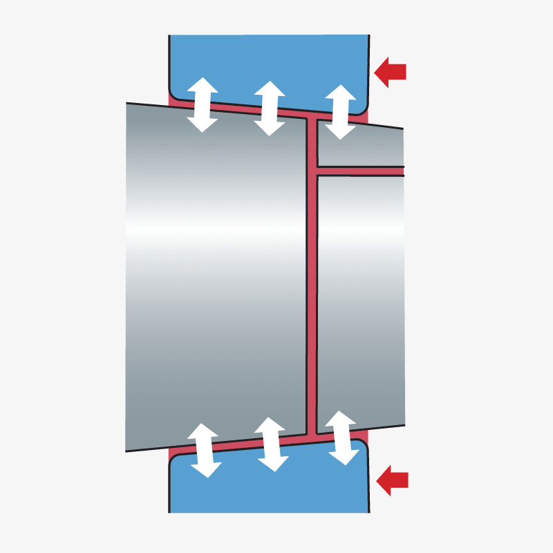
Injecting the oil between two tapered surfaces will create a reaction force which could be quite substantial as the oil will also act as a “hydraulic cylinder” which can push the outer component off (fig 7).
The preparation
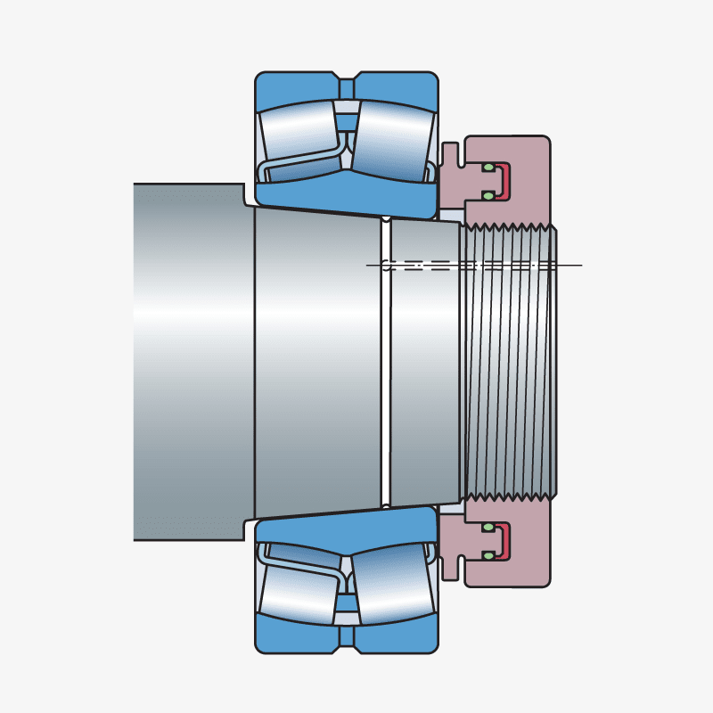
During manufacture, the shafts are prepared with oil ducts and grooves. For technical information on how to prepare the shafts, consult an SKF application engineer (fig 8).
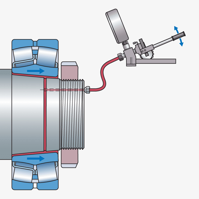
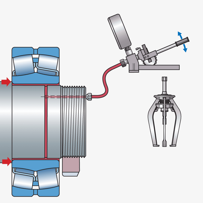
The action
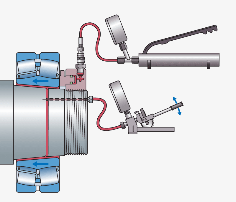
Bearings are dismounted by injecting oil between the mating surfaces and when sufficient pressure is reached, the bearing will be pushed off. A nut is required to keep the bearing from sliding off the shaft (fig 9).