Transmission capacity
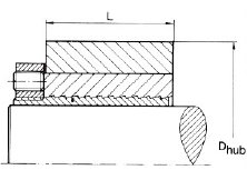
The table gives the required minimum hub diameter (Dhub) for various materials when the SH bushing is completely covered by the hub (fig 1).


fig 1
Designation example
Bushing with slotted outer components for 20 mm shaft = SHT 20.
Width of hub smaller than bushing
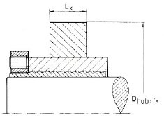
If the width of the hub is smaller than L (fig 2), the hub diameter must be multiplied by the factor fk obtained from diagram 1.


fig 2
Example
SH bushing SHT 40
Hub material yield limit Rp 0,2 = 200 N/mm2
Hub width Lx = 31,5 mm
Hub material yield limit Rp 0,2 = 200 N/mm2
Hub width Lx = 31,5 mm
The required minimum hub diameter is obtained as follows:
Lx/L = 31,5/45= 0,7
From the diagram, fk = 1,18
Minimum hub diameter = Dhub fk = 89 × 1,18 = 105 mm
Lx/L = 31,5/45= 0,7
From the diagram, fk = 1,18
Minimum hub diameter = Dhub fk = 89 × 1,18 = 105 mm
Simultaneously acting torque and axial force
If the joint is simultaneously subjected to a torque and an axial force, the resultant torque is obtained using the equation:
MvR = √(Mv2 + (Pax d/2 000)2)
where
| MvR | = | maximum resultant torque [Nm] |
| Mv | = | torque acting on bushing [Nm] |
| Pax | = | axial force acting on bushing [N] |
| d | = | shaft diameter, mm |
Example
Bushing SHT 50 is subject to an axial force of 20 000 N and simultaneously to a torque of 500 Nm. The machine factor fd is estimated as being 1,5.
MvR = √(5002 + (20 000 × 50/2 000)2) = 707 Nm
MvR = √(5002 + (20 000 × 50/2 000)2) = 707 Nm
According to the table, the maximum torque for SHT 50 is 1 625 Nm. The permissible torque is then:
1 625/1,5 = 1 083 Nm
1 625/1,5 = 1 083 Nm
Load transmission
The maximum static slip torque and axial slip force are given in the product table. Under dynamic load, the transmission ability is obtained by dividing by the machine factor fd (table).
