Gear couplings
Gear couplings are torsionally rigid and are supplied to two designs – completely flexible and flexible/rigid. A completely flexible coupling comprises two hubs with an external gear and two outer sleeves with an internal gear. It’s a universal coupling for all sorts of applications and accommodates all possible misalignments (angular, offset and combined) as well as large axial moments. Machines, bearings, seals, and shafts are therefore not subjected to the additional forces, sometimes of considerable magnitude, which arise from unavoidable misalignment usually associated with rigid shaft couplings.
A flexible/rigid coupling comprises one flexible geared half and one rigid half. It does not accommodate parallel displacement of shafts but does accommodate angular misalignment. This type of couplings are primarily used for “floating shaft” applications.
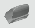
Sizes 010 – 070 all have crowned teeth with a 20° pressure contact (fig 1). This enables to accommodate up to 1,5° static angular misalignment per gear mesh. However, minimizing the operational misalignment will maximize the life of the coupling as well as the life of other machinery components such as bearings etc.


fig 1
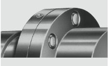
Each sleeve flange is supplied with two pipe plugs 180° apart. This permits assembly of a full flex-coupling with four lubrication plugs positioned every 90° apart, to facilitate lubrication (fig 2).


fig 2
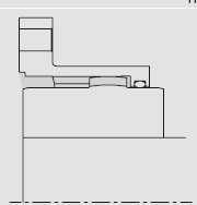
A Buna-N O-ring is fitted to the outer sleeve, to retain grease and exclude contaminants (fig 3).


fig 3
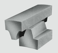
A straight faced tooth form is used for the sizes 080 to 300 (fig 4). They are de signed to accommodate 0,5° misalignment per gear mesh. These sizes are also equipped with a removable end ring for ease of assembly and to allow inspection of the gear teeth. KSG grease is recommended in order to obtain maximum operating life. Refer to the section Lubrication for further information.


fig 4
